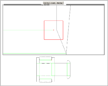
This function isolates and zooms in on endpoints that do not fall on another end point or another significant piece of geometry. The Gap Detector works only on the Die layer. Be sure to run the Gap Detector before you do any notching. The Gap Detector is best used right after the “Make Die Sheet” function, when everything is just getting started. The design being checked is displayed below the main Gap Detector window. The Zoom Window and has a red rectangle drawn around the offending point.

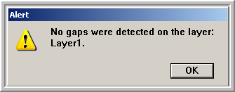
When using the Gap Detector, the Select Tool is engaged by default. This is the most versatile tool for correcting gaps since it performs a variety of point, line or entity moves. Fix the gaps by dragging points or adding and deleting geometry in the zoomed window. You can use any of the other tools needed to fix gaps live inside this window. Choose “Next” or “Last” from the buttons on top to loop through the gaps in the design. Choose “Cancel” to quit checking for gaps. If no gaps are found in the design, you will see a dialog box confirming this.

When you have cycled through all the gaps, you will return to the view you where you started the Gap Detector. If the Gap Detector shows a gap but it doesn’t look like there’s one in the Zoom Window, zoom in further on the point inside the Zoom Window that is outlined in red. You’ll see it. The tolerance is factory-set to .003” to prevent “fall out” from laser cutting. The gaps sometimes are very small and hard to see. This gap tolerance setting can be changed in the Prefs.fe file.