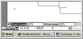
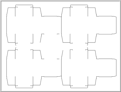
The Jiggernaut Tool is designed to aid in the creation of male and female jig fixtures for Bobst die cutting machines. This tool will create dual offset geometry at preset distances of closed shapes within a design. For many common designs, a combination of the Jiggernaut Tool and the Make Jigs function will create fully finished fixture sets automatically. Some designs will require tweaking the geometry to get it perfect. How much tweaking or editing required depends on the design. The Jiggernaut can be run before or after the Choppernaut but it must be run before using the “Make Jigs” function. The Jiggernaut Tool makes male and female parts of the fixtures from the interior cutout areas and the exterior of the design outline. The Jiggernaut runs a similar function as in the Choppernaut and requires that the pieces to be jigged are closed objects. A design as shown below should have connecting geometry between the designs to provide a closed object for the Jiggernaut.
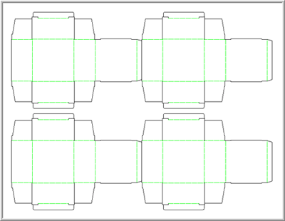
This is a simple four-out straight tuck design with a 1” gutter. The gutter is a problem for the Jiggernaut since the intention is to make a fixture that pushes the scrap away from the design. Add connecting lines on each end of the design to give the Jiggernaut boundaries for its fixtures.
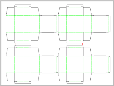
This design has two areas that need the Jiggernaut Tool: inside the middle of the design and around the outside of the design. Choose Flat Dies → Jiggernaut to start the tool.
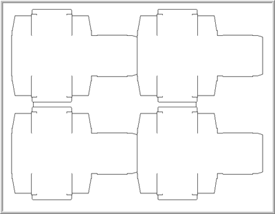
The Tool will place the knife from the design on a temporary layer so that it is easier to work with. Your cursor will now appear to be a small jigsaw blade. The Jiggernaut places the male offset geometry to the side nearest the click and the female geometry on the opposite side of the boundary line of the shape. Click inside the middle area of the design to create the first set of offsets. Zoom in on the area far enough so that the Drafting Assistant doesn’t try to lock on to anything. You should be clicking in empty screen space, not on any geometry.
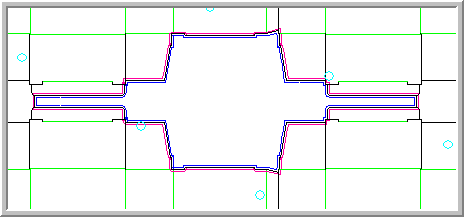
You will see a very fast trace of the area occur and the screen will flash and return to full screen zoom. Notice that the area that you just jigged “disappears” from the screen. This indicates that the area has already been jigged. This design still needs another click of the tool to finish the Jig parts but there is a problem. The connecting geometry has already been used on the inside jig so the tool will fail if used again to perform the outside jig. Choose the Select Tool from the main tools palette and you will automatically return to the die design. The jig piece you just did should be there and will look like this.
Choose Flat Dies → Jiggernaut again to return to the Jiggernaut tool with the connector lines restored for further use. When you get back into the Jiggernaut, your screen will look like this again:
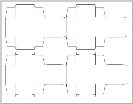
Click outside the design to create the outside part of the fixture. The outer edges of the design will flash and disappear like the inside did, letting you know that the process was completed. Your screen will look like this:
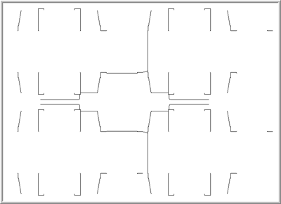
Choose the Select Tool or move on to any other operation to return to the die design area and complete the design. When you return, the die will contain the areas jigged by the Jiggernaut Tool. Inspect all the areas of the offsets to make sure no overlapping geometry was created. Overlapping geometry can be created by the offsetting action of the Jiggernaut Tool on tight angles. Remove overlapping geometry before proceeding with the Make Jigs function. Set the default offset distances used by the Jiggernaut Tool by editing the Prefs.fe file. You can adjust the offset distances on the fly by entering an amount of Offset In and or Offset Out in the feedback boxes at the bottom of the screen before clicking in the area to be jigged.
